基于STM32控制的大功率直流电机调速系统
内容简介
 第4期 2017年4月
组合机床与自动化加工技术
Modular Machine Tool & Automatic Manufacturing Technique
文章编号:10012265(2017)04011103
DOI : 10. 13462/j. cnki. mmtamt. 2017. 04. 028
No.4 Apr.2017
基于STM32控制的大功率直流电机调速系统
吴攀,周风星
(武汉科技大学信息科学与工程学院,武汉430081)
摘要:针对直流电机调速系统大功率高精度的控制需求,设计了一种基于STM32单片机和H桥的新型控制系统。该系统使用光电编码器作为速度检测传感器,利用光电隔离器设计了一种大功率直流电机驱动控制电路,直流电机利用PWM脉宽调制以及PID算法实现对直流电机速度,启停,转向准确控制。上位机采用LabVIEW编写,实时监控直流电机运行状态。描述了硬件的设计方案。通过
实验结果表明,该直流调速系统具有调速精准,低功耗,大功率的优良工作特性。关键词:STM32控制;H桥;大功率驱动
中图分类号:TH166;TG506
文献标识码:A
Research on High-power Velocity Regulation of Direct Current Motor Using STM32 Control Processor
WU Pan,ZHOU Feng-xing
( College of Information Science and Engineering, Wuhan University of Science and Technology, Wuhan 430081,China)
Abstract : According to the control demand of velocity regulation of DC motor with high-power and high precision, a new kind of speed regulation system based on STM32 microcontroller and H-bridge driver was designed. The speed regulation system make use of PWM and PID algorithm as output signal to controlling starting, braking, positive inversion and speed regulation of DC motors, which by using photoelectric coder as speed detecting sensor and optoelectronic isolator to design a high-power driver circuit . The parameter da-ta of the DC motors was monitored and written by LabVIEW in PC. The hard circuit design were described in this paper. Experiment proof show that this kind of speed regulation system for DC motor has the charac-
teristics of precise speed regulation, low-power consumption and high driving power. Key words; microcontroller STM32; H-bridge; high-power driver circuit
0引言
社会生产中,大功率交流电机的应用非常普遍与成熟,但在只有直流电源的应用场合下,大功率高精度的直流电机调速系统")就十分稀缺。目前,国内外直流调速系统设计研究主要集中于小功率灵活化,例如大多数文献研究资料采用IR2104,IR2110 系列驱动芯片,采用这些芯片设计的小功率直流电机调速系统,驱动电流不超过5A,只能应用于小功率直流电机,针对这个问题,本文设计了大功率直流电机调速系统。
系统总体结构 1
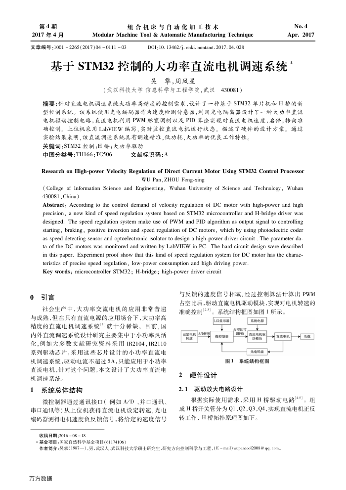
微控制器通过通讯接口(例如A/D、并口通讯、串口通讯等)从上位机获得直流电机设定转速,光电维码器测得电机速度负反馈信号,将给定的速度信号
收稿日期:20160818
与反馈的速度信号相减,经过控制算法计算出PWM 占空比后,驱动直流电机驱动模块,实现对电机转速的准确控制[2-3]。
系统结构框图如图1所示。
Lp显示器
设定电积m
转通
2
微控制器
系族电源
卢空此可
、直视电机票
动模块光电码盘
图1系统结构框图
硬件设计
2.1
驱动放大电路设计
+直流电机
+负款
根据实际使用需求,采用H桥驱动电路143]。组成H桥开关管分为Q1,Q2,Q3,Q4,实现直流电机正反转工作,H桥拓扑原理图如下。
*基金项目:国家自然科学基金项目(61174106)
38000()(86)万方数据