您当前的位置:首页>论文资料>扇形轴疲劳失效断裂原因分析
内容简介
 杨振宁李风民赵清华李传坤:扇形轴疲劳失效断裂原因分析扇形轴疲劳失效断裂原因分析
杨振宁李凤民赵清华李传坤(山东滨州渤海活塞股份有限公司)
27
【摘要】某扇形轴在疲劳试验时出现断裂现象,见图1。拆卸后发现在57×104图时断裂。
通过对扇形轴进行宏观检验、金相检验、硬度测试、化学成分分析、扫描电镜分析和能谱分析,对该扇形轴失效原因进行分析和探讨。结果表明:扇形轴裂纹从晶粒间的内氧化开始,沿晶界向内延伸。说明晶粒间的内氧化促成了扇形轴的疲劳失效。受到其他因素的影响,如装配、尺寸偏差、工作负载等等,也可能使扇形轴因疲劳失效而断裂。
【关键词】扇形轴内氧化沿晶脆性开裂
Summary: the sector shaft cracked during the fatigue test, see fig. 1. It' s discovered after dis-mantling that the sector shaft cracked at in the 57 × 104 round. Failure cause of the sector shaft is ana lyzed via macroscopic inspection, metallographic inspection, hardness test, chemical composition analy-sis, scanning electron microscope analysis and energy spectrum analysis. The analysis result shows that : the crack starts from the intergranular intemal oxidation, and extends entad. It explains that the interg-ranular internal oxidation caused the fatigue failure of sector shaft. Other factor such as assembly, dimen-sion deviation and working load may also cause the fatigue failure.
Key words: sector shaft; internal oxidation; intergranular brittle cracking
该扇形轴材料为20MnCr5,其设计寿命不小于100×104圈,在57×104圈时断裂。生产流程如下:锻造机加工渗碳率火退火喷丸打磨。喷丸是扇形轴螺纹的最终工序。失效件在螺纹处损坏。通过与超过100×104圈疲劳测试的正常件进
行对比分析。 1
理化检验
1.1宏观检验
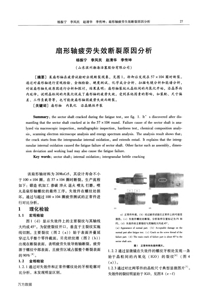
图1(d)显示失效件上的主要裂纹与其轴线大约成45°。为促使裂纹开口,垂直于主裂纹实施线切割。主要裂纹(图2(a))始于表面并蔓延穿过几乎整个零件截面。贝壳状纹理(图2(b))出现在断裂表面,表明疲劳失效导致轴断裂。疲劳源于螺纹中部表面,且疲劳区域占据整个断裂表面的90%[8]
1.2金相检验
1.2.1通过对失效件和正常件螺纹处的牙根轮席对
比分析,未发现明显区别。万方数据
)正常件外观。(b)经过疫劳试验后正常件上的可接受损伤。(e)失效件螺纹处断裂。分析取样位置标记为PI和 P2。(d)失效件的主要费纹与其轴线大约成45°。
(a) Appearance of nomal par. (b) Aceptable damage on the normal part after fatigue test. ( e) Crack on the screw thread of the failure part. (d) The main crack of failure part is about 45*to the sector shaft axis
图1正常件和失效件照片。
1.2.2通过显微镜在失效件的螺纹牙根处发现一条始于晶粒间的内氧化(IGO)的裂纹(6)(图4(a))。
1.2.3通过对比两零件的晶粒尺寸典型显微图片[7]。失效件的裂纹明显始于ICO,见图8(e~f)
上一章:机械加工时一种新的工件找正方法
下一章:浅析如何提高合金铸铁环的弹性模量